MkII Cortina Perana V6 racer

Pictures of your muscle car!
User avatar
KSF
Posts: 325
Joined: Fri 07 Feb 2014, 15:07
Location: Western Cape

Re: MkII Cortina Perana V6 racer

Post by KSF » Fri 04 Nov 2016, 15:05

ZA Perana wrote:.......a car many had forgotten about and that colour scheme just looks amazing.
True that. A lot of really nice cars of that era is lost to the collective memory because they are drowned out by the Perana/CanAm battles (which ended up actually being a very brief period).

Here below is another. While looking for another Capri shell to build a new car, this is the one I had in mind. I hope someone builds one one day. Or maybe after the Cortina I might take on another project and build one.
Argus - John Taylor Capri V6.jpg
Argus - John Taylor Capri V6.jpg (413.33 KiB) Viewed 3727 times
Argus - Peter Gough Capri V6 Kyalami 1970.jpg
Argus - Peter Gough Capri V6 Kyalami 1970.jpg (113.88 KiB) Viewed 3727 times

User avatar
KSF
Posts: 325
Joined: Fri 07 Feb 2014, 15:07
Location: Western Cape

Re: MkII Cortina Perana V6 racer

Post by KSF » Fri 04 Nov 2016, 15:17

zahistorics wrote:the suspension setup was so crazy the car was three wheeling severely. Koos said the left side of the car was so high in the air as he came up on a Monaro that he could no see it.
Back in those days, most had a firm belief that the back end of the car must be set-up quite soft. The theory was that the more compliant set-up would aid traction and help keep the inside wheel down (not all used or were allowed to use LS diffs). The result was the classic 3-wheel stance of the era.
Ford-08.jpg
Ford-08.jpg (44.83 KiB) Viewed 3725 times
Here is another in battle with the Capri.
Ford-07.jpg
Ford-07.jpg (66.18 KiB) Viewed 3725 times
22.jpg
22.jpg (36.95 KiB) Viewed 3725 times
KYALAMIWINTERRACE.jpg
KYALAMIWINTERRACE.jpg (190.07 KiB) Viewed 3725 times

User avatar
KSF
Posts: 325
Joined: Fri 07 Feb 2014, 15:07
Location: Western Cape

Re: MkII Cortina Perana V6 racer

Post by KSF » Fri 04 Nov 2016, 16:29

So back to my project: With the engine and gearbox suspended in position it was time to see about fitting a crossmember and suspension, steering, engine mountings etc.

Side note on this: The originals used a steering box with the steering arms behind the cross member. This worked with the sumps they used back then where the oil reservoir was in front. It has two implications: using that front sump, you cannot move the engine back and it is some 50-70mm further forward than it can be. Using the later model rear sump, it ends up a serious battle to fit it in and still clear not only the steering arms, but also the crossmember.

So, since it is allowed in our class of racing to convert from steering box to rack and pinion, I decided to go the route of a rear sump with the steering and crossmember from a Sierra. There might be some 10-15 years difference between the Cortina and Sierra, but the basic layout and functioning of the two are the same, biggest difference is that the Sierra ARB sits behind the cross member and the Cortina in front. So the ARB get turned around and you swop the two lower controls arms left to right. Everything else remains. The cross member needs some modification as the Cortina chassis rails is a fair bit narrower. In the process you also lose the posts for the engine mounts.

Pic below the suspension sits on a trolley jack somewhere through the process of trial fitting, modification and refitting.

Photo0817.jpg
Photo0817.jpg (62.18 KiB) Viewed 3723 times
It fitted quite well and with a slight offset, the steering column knuckle at the bottom made it in too. Lower control arms locations were modified in any case, so the offset gets corrected there. Also, just to be sure no-one cries foul over this, I used the exact same OEM mounting holes to secure the cross member to the chassis rails. Sorry, no pics from under the car available. I tended to just takes pics after work was done, so to speak.

With all this in place, I started in on engine mountings. This was a bit of a head scratch-er as I did not want to use the big and heavy Sierra type mountings. Space too limited anyway. For the Cortina type of V mountings, the rack and knuckle was in the way on the one side. In any case, space was limited and more stuff had to be squeezed in there later. So I took my que from my mate Jackie's build of the Taunus (which I took apart and am using much of the parts for this car, that front suspension comes from there) and decided to mount it directly to the Cortina's chassis rails. The parts I pirated off the Taunus was close and with a bit of modification and trimming it worked.
Photo0822.jpg
Photo0822.jpg (70.18 KiB) Viewed 3723 times
You'll see in the pics I added some reinforcing to the chassis rails. The rails are quite thick, in total perhaps 3mm or so. I added additional 2mm plate to the top and sides. the MMA welding with invertor welder and 2mm rods work well enough. You could just about get runs going, instead of the endless short stitches employed on the thinner stuff.
Photo0823.jpg
Photo0823.jpg (69.58 KiB) Viewed 3723 times

User avatar
KSF
Posts: 325
Joined: Fri 07 Feb 2014, 15:07
Location: Western Cape

Re: MkII Cortina Perana V6 racer

Post by KSF » Fri 04 Nov 2016, 16:53

With the engine finally supported it was time to sort out the g'box tunnel and support. The OEM crossmember and its mounting position is quite far away from what is required for the Type9. Also the mounting position was too narrow and too far forward. It consists basically of an extra panel, roughly horse shoe in shape that is spotwelded to the inside of the tunnel. I removed that completely.

In its place I added some reinforcing plate around the outside of the tunnel (ie inside the car), deliberately shaping it on a slightly different curve to create distance between it and the tunnel. It adds to the strength and rigidity of where the gearbox will hang. At its base on the car's floor sit some 5mm plate with hi-tensile 8mm bolts welded in. Under the car they appear as studs.

For the rest of this I just made two covers, one to repair the "hacked" bit and another to cover the OEM gearlevel hole. Pics below the whole lot is already covered in NS1 for the night, so not a lot of detail visible. All that also welded in place.
Photo0838.jpg
Photo0838.jpg (66.49 KiB) Viewed 3718 times
You might notice, to the left of the tunnel lies a bit of metal, thick and with a bend in it. Sharp eyes will see the arc strikes on it. It is a very usefull thing to have for MMA in general but especially when you work with low amps on thin walled stuff. You used that at first to strike on with a new or already used but cold/cool rod. It gets it warmed up and the flux ready to produce the shielding gas. Once it is warmed up like that, it is much easier to get a steady arc going and you don't make a mess of trying to get it going by dragging it all over or getting stuck etc.
Photo0837.jpg
Photo0837.jpg (77.15 KiB) Viewed 3718 times
With that done it was the relatively simple matter of modifying a Sierra crossmember (or maybe it was a V6 Cortina one I used) to fit. Sorry, no pics.

It was by now the week before Xmas of 2014. Time to pack it in for the year and put feet up for a bit. A big-ish headscratcher was next, exhaust branches that will fit in the small space available! :| :?:

User avatar
KSF
Posts: 325
Joined: Fri 07 Feb 2014, 15:07
Location: Western Cape

Re: MkII Cortina Perana V6 racer

Post by KSF » Mon 07 Nov 2016, 17:07

KSF wrote:
IndianaJones wrote: Why the Type 9? If I may ask. Do you need an overdrive? Isn't the 4-speed "Bullet" box much more reliable? And lighter?
Short question with potentially a long answer.... :)
And just to make it a bit longer still, it may be worth adding in what you are allowed to use. The rule says you can use any "production based" gearbox, does not have to be manufacturer original or original manufacturer. In addition, you are allowed to swop out the internals for specialist aftermarket parts. It leaves the door quite wide open and if you wish to throw money at it, you can.

User avatar
KSF
Posts: 325
Joined: Fri 07 Feb 2014, 15:07
Location: Western Cape

Re: MkII Cortina Perana V6 racer

Post by KSF » Mon 07 Nov 2016, 17:31

So Xmas 2014 came and went, January rolled around and work on the project got going again. The next step was to see if I could get exhaust branches to fit in the engine bay.

Needless to say, you don't just go and buy a set for a V6 Cortina MkII, so your options are limited to custom made parts. Or I guess you could fit the std cast iron units off one of the models, which ever fits best. As mentioned, my plan was to use as much as possible of the parts salvaged from the Taunus project for this car. The Taunus had some TnT Cortina 'Racing' branches. Not a straight fit, but a decent starting point perhaps. Their 42mm OD is just about right for Killarney and the type of engine I had in mind. The individual lengths could be a lot better and once I saw they needed some work to fit, I ended up chopping them into pieces and rebuilt the puzzle.
Photo0812.jpg
Photo0812.jpg (75.99 KiB) Viewed 3679 times
This is one set after a mock-up. Masking tape is quite usefull to hold the pieces together and allow some finer adjustments as you go along. They are a work in progress, but I am happy that I got them all to neatly fit in there and exit the engine bay area cleanly. All are just about the same length and probably already long enough, but perhaps another 100mm wont hurt.
Photo0870a.jpg
Photo0870a.jpg (39.87 KiB) Viewed 3679 times
Since these pics I did weld them up, making up the pieces to carefully close those gaps with inserts. You may wonder about how much that affects airflow and performance when compared to well shaped mandril bends? So long as the welds don't over penetrate and you don't create steps when joining or mitering like that, there really is not a lot in it.

User avatar
KSF
Posts: 325
Joined: Fri 07 Feb 2014, 15:07
Location: Western Cape

Re: MkII Cortina Perana V6 racer

Post by KSF » Tue 08 Nov 2016, 16:28

Branches were set aside to complete another day, as would be the rest of the exhaust system.

Next step of this fabrication and mock-up stage was to get the front suspension in completely. Up to now I had the crossmember and steering rack in. To go on next were the struts with hubs, lower control and ARB.

To start with I redrilled the lower control arm locating holes in the crossmember to compensate for the 10mm offset of the cross member. (The offset was required to get the rack's pinion end to clear the narrower chassis beam on the driver's side). With the struts in place and the tops just rattling around in the turrets, I propped them up on axle stands to the approx rideheight position. For this exercise the struts were assembled without the springs.
Photo0839.jpg
Photo0839.jpg (50.97 KiB) Viewed 3650 times
The ARB then had to be located under the front of the car. Again not a bolt on, I made up some brackets and adaptors to bolt to the original positions (plus some reinforcing). To this bracket the Sierra's much thicker ARB now bolts, using its own U-brackets and rubbers. The rubbers will ultimately be replaced with poly parts. Positioning of the ARB in its height and front to back position is important as it impacts on the suspension geometry. The angle from its mounting to the lower control arm decides if you get anti-dive characteristics or dive characteristics. On the Cortina it not difficult to get about right, by contrast on a Capri it is not easy to do because of the shape at the front. Big spacers are usually required which causes the ARB to 'hang' out the bottom.

The front to back (other than locating the wheel hub in the centre of the arch) is also used to gain a bit of castor (originally they don't have a lot). I have no pics of this work at this time, but will get back to it later on during finally build/assembly.

This left the top of the strut to be located. It also opened a lengthy debate among the team members (the group of Ford fans consisting of family and friends that build and race) about the merits of using an adjustable set-up at the top or not. Camber plates (the popular ones have vernier adjustment) are in vogue with many racers and offer many advantages. Biggest being the ease of adjustments to camber and castor. It is a must for competitive racing and especially so if you race on more than one circuit.

For club racers like us who do 95% of our racing at Killarney only and even then in 'club' events with time based classes, the benefits are not so clear cut and obvious. In addition, the car I am copying was raced in what was then called Production Cars and would not have been allowed camber plates. I dont have a very strong opinion one way or the other, but decided in the end to not use them. I know with a fair degree of accuracy what camber and castor I want and I do have other means of doing fine adjustments. So I decided to simply weld in a top to fix it in position. This uses a piece of Sierra strut top cut out and welded into the Cortina top, which also needed some modifications. Plus it called for making up a piece to fill in the big gap around the front. Pictured below this set-up midway through the welding process.
Photo0844a.jpg
Photo0844a.jpg (47.2 KiB) Viewed 3650 times
This was again the invertor and 2mm rods. The pic was after the first runs and shows that although I got good welds around the front, around the inside and the back I made a mess. It calls for a very thorough clean up and digging out flux etc. Not ideal and here a gas shielded process (MIG or TIG) would be much better.

User avatar
KSF
Posts: 325
Joined: Fri 07 Feb 2014, 15:07
Location: Western Cape

Re: MkII Cortina Perana V6 racer

Post by KSF » Tue 08 Nov 2016, 16:58

The last piece of that particular puzzle was getting a steering column in place. OEM Cortina column is integral part of the steering box which I removed. One could alter it with some modifications to work with a steering rack, but since I had the column that came out of the Taunus and I found on offering it up to the car that it just about fitted straight in with minimal changes required, I went that way. Originally it comes off a MkIV or V Cortina. It had been altered to extend further away from the dash already, so much time and effort safe. Some minor adjustments to the mounting and new holes drilled under the dash sorted out its location there.

At this time (because they have to be positioned together) I also worked on getting a pedal box in the car. The OEM parts were in sad state and pedal missing. It also would not work with the master cylinders I wanted to use, nor the cable for throttle operation. These Cortina's used a system of levers and links to the carb, no cable. So the whole pedal box went and along with the steering column, I started massaging the whole pedal box from the Taunus in there. It took some trimming here and there, also significant modification of the firewall's holes and locating bolts, but it is in, works with the steering column. Not many pics, but can be seen on some of he pics to follow.

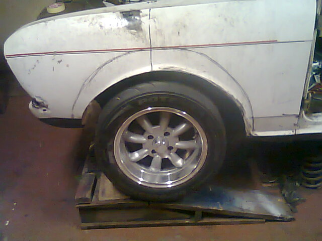
Finally it was time to put a wheel on the car to see how it would work with the mudguard, where the flare needs to be , how high and so on.
Photo0846.jpg
Photo0846.jpg (56.52 KiB) Viewed 3646 times
At the ride height and width of the wheel, it fouled completely, so pictured here the arch already has its lip trim off. The wheel is also lowered to get it clear for work on the arch.

I wanted to try and copy the original car's flare shape as close as I can. The photographs I do have only give me an idea though, not a clear picture. Also, I believe those original arches were wider than what we are allowed today by our rules (nominal 2" or 50mm wider than std). So some compromises has to be made.

A popular flare here at the moment is to buy a set of Golf 1 front fenders (they're cheap enough) and then cut the flare out to weld onto the car to be flared. Another way is to buy one of the ready made glassfibre flares that guys sell. They are 50mm wide and look period correct too. Neither of those options would work for me (size and shape) and in any case I am not a fan of those Golf arches.

So I decided to make my own flares again, similar to what I did on the Capri. It takes a while, lots of work and takes time to finish off properly. But you do get to make them exactly like you want them. There are other ways to skin this cat, what I show here is my preferred way.

It takes some marking out and measuring and marking, lots of it.
Photo0847.jpg
Photo0847.jpg (68.62 KiB) Viewed 3646 times
I had a cardboard template around this lot, marking and recording dimensions. This is important, because shaping this one flare is tough enough, then you have to go and make its exact mirror image on the other side. So anything to help you transfer the shape and dimensions to that side helps.
Photo0848.jpg
Photo0848.jpg (49.67 KiB) Viewed 3646 times
This pic above is the other side, the repaired mudguard.

User avatar
KSF
Posts: 325
Joined: Fri 07 Feb 2014, 15:07
Location: Western Cape

Re: MkII Cortina Perana V6 racer

Post by KSF » Tue 08 Nov 2016, 17:20

After the tranfer of pattern from left to right with permanent board marker (it later turned out to not be permanent ! :( ) you get to make lots of noise as the cuts are made with an angle grinder and 1mm cutting disc. You could also simply cut them with tinsnips (the metal is thin enough), but it deforms it too much to my liking and they edges keep catching on one another. Or if you really like pain, cut them with a hacksaw.

In the pic in the previous post I put an old blanket over the wheel for protection.

With that done and all the available photographs printed out and on hand, you start shaping those individual tabs (or tongues?). Maybe leafs is a better word.
Photo0849.jpg
Photo0849.jpg (63.91 KiB) Viewed 3645 times
I have no clever way of doing this, it is done by hand, by plier, vicegrip, what ever tool comes to hand and seems right. There is a fair bit of trial and error to get the desired shape.
Photo0850.jpg
Photo0850.jpg (71.85 KiB) Viewed 3645 times
This is the first rough shape, then the wheel gets lifted to ride height to check clearance and appearance.
Yes, my companion and chief inspector, Queeny, gave input as well.
Photo0851.jpg
Photo0851.jpg (56.89 KiB) Viewed 3645 times
Pictured above she may have indicated disapproval....
Photo0852.jpg
Photo0852.jpg (66.22 KiB) Viewed 3645 times

User avatar
KSF
Posts: 325
Joined: Fri 07 Feb 2014, 15:07
Location: Western Cape

Re: MkII Cortina Perana V6 racer

Post by KSF » Tue 08 Nov 2016, 17:37

An aside post about flares. Back in the day of the V8 Capri Perana's, when they were first raced, some of the racing preparations were done with great urgency and haste to get the car on track. Then it was the national format of racing.

Pictured below is the lilac Perana at K.
CAPRIS-Flares.jpg
CAPRIS-Flares.jpg (434.55 KiB) Viewed 3644 times
Not very clear on this one, but the flares were white and the rest of the car lilac (light purple). Far from being a style statement, those flares were put together in a great hurry the day before and were in fact cardboard and tape! :D

Later with more time in hand it was done properly and made what is one of the best looking Perana racing cars of the era.

PGCAPRIPURPLE.jpg
PGCAPRIPURPLE.jpg (266.49 KiB) Viewed 3644 times

Post Reply

Social Media


Who is online

Users browsing this forum: No registered users and 12 guests